
Delay-Line Detectors with Hexanode
Unlike most other MCP detector systems, RoentDek delay-line detectors such as DLD40 and DLD80 have a high ability to detect multiple particle hits (multi-hits) and analyze the position and time coordinates (“3D detection”) of each individual particle (hit).
However, if the relative arrival time (timely pulse pair distance) between two individual hits is of the order of the electronic pulse duration in the front-end electronics or below, the information on these hits might be lost or become ambiguous. Furthermore, the pulse-pair resolution limit (pulse-pair dead time) of the used multi-hit TDC can impose another limitation on the acceptable timely pulse pair distance, e.g. for the RoentDek detector system with multi-hit TDC the pulse-pair dead time is 10-15 ns. If two hits are closer in time they can still be recovered if the relative distance in x and y position exceeds a certain value (for details, please see this link). Of course these considerations are also valid for a particle shower with more than two hits. Then the smallest timely pulse pair distance between any two hits applies for the above considerations.
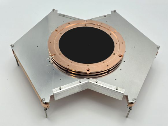
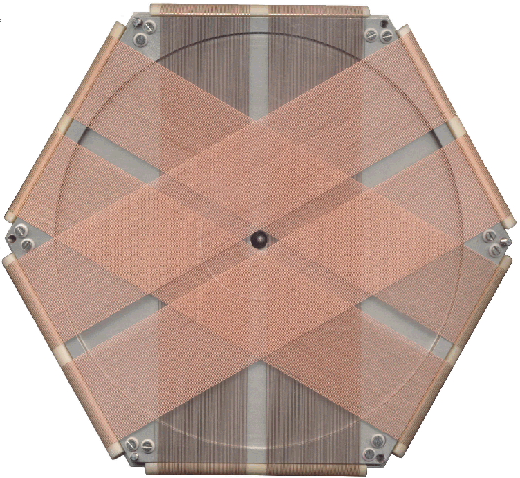
To improve the multi-hit ability in the region below 10 ns timely pulse pair distance, RoentDek has introduced a delay-line detector system with the novel hexanode. It is similar in many respects to the standard DLD detector system, but the hexanode has a third independent delay-line layer, i.e., three delay-line layers are mounted with a relative angle of 60°. Signals from any two of the layers are sufficient to give a performance according to the standard DLD detector (with two perpendicular delay-line layers) as described above. But it can be shown that by having a redundant third delay-line layer a complete and unambiguous recovery of multi-hits (with two or more particles) can be done if the relative timely OR spatial relative distance between any two hits is above the pulse-pair dead time Dₚₚ or Dₚₚ×v, respectively (see this link). In easier but less precise words: the hexagon delay-line anode is only blind for a hit pair if the particles come at the same time AND at the same position.

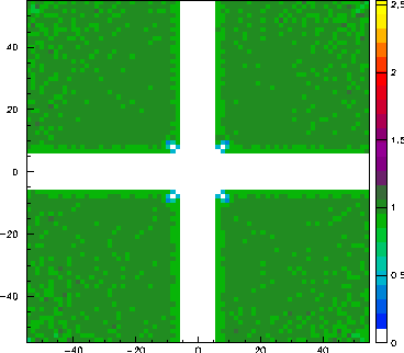
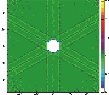
This situation of particle pairs arriving at the same time AND at the same position is very often excluded for physical processes as for example in case of a breakup of molecules (see next figure). For such processes the hexanode removes any limitation of the delay-line method for multi-hit detection.
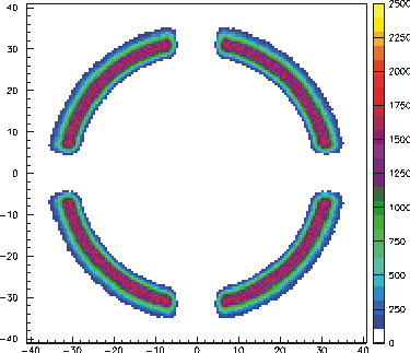
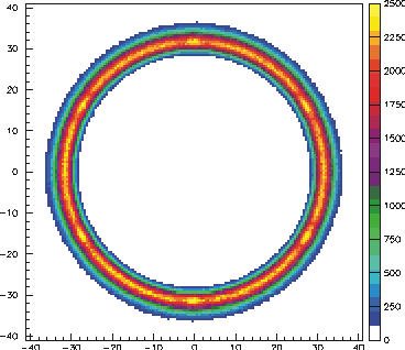
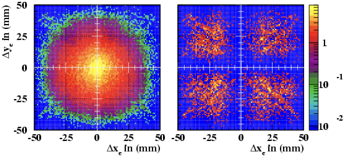
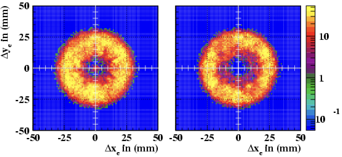
A triple-layer coverage also allows the construction of delay-line detectors with central hole (these special detector designs with central hole do not provide multihit capability).
The multi-hit ability of the hexanode brings up the idea of using it for doubling count rate in experimental situations where only single hits are of interests but event rates are limited by the repetition rate of the ionizing source. An example is laser-driven ionization with fix rep rate but where the particle yield can be tuned (modifying intensity or target density) in the sense that more than one particle per shot is released towards the detector (see this link).
There are also other reasons for using a hexanode in applications where multi-hit ability is not the main issue. The same redundancy that allows for an advanced multi-hit recovery also enables determination and correction of image non-linearity, which is to some extent inherent to the individual delay-line arrays on any DLD. For the Hexanode an inherent calibration map can be produced which allows to improve global imaging linearity for single and multiple hit events. Moreover, it is possible to determine spatial linearity and also the local resolution in an acquired image without need for using a test mask (see figure below).
